
Allegro X System Capture Front-to-Back Flow Training
By Jarrett
General Notes
Section titled “General Notes”-
Here is the link to the course.
-
Follow the same steps as above for starting this project; however, DO NOT download the lab database into OneDrive (or any form of online storage), as this may cause problems later in the course
-
I actually enrolled in the 22.1 version of the course but used the 17.4 version of the software, and I did not encounter any issues. Currently, we are using the 17.4 version of the software due to the 22.1 version not being fully licensed for Clemson students yet.
-
When the lab PDF tells you to save the project, and an error comes up when you do this, first check if the lab PDF says anything about errors coming up. If it does, you are good to move on. If it does not, click on the error to see if you can fix it before moving on.
Requirements
Section titled “Requirements”-
Access to System Capture 17.4
-
Access to Project Manager 17.4
-
Access to PCB Editor 17.4
-
Completion of the Design Entry HDL Front-to-Back Flow and Design Entry HDL Basics courses is recommended
Introduction
Section titled “Introduction”This course introduces yet another schematic design application, the System Capture app. The unique aspect about this app is that it allows for users to import designs or libraries from other applications such as DE-HDL and OrCAD Capture. System Capture also gives users access to parts from external libraries. Using the System Capture software is fairly similar to using the previously discussed schematic design apps and this course will give a similar overview covering placing parts, drawing wires, generating netlists, etc…
Module 1
Section titled “Module 1”Module 1 of the course simply contains an overview of what the course will cover. It is still important to read over this and gather an understanding of what you will be learning. Before starting the course you should head to the Database Downloads module of the course. On the Module 1 page, click “Database Downloads” and save the folder “Lab Database” to a location on your computer. I recommend making this folder easy to access as you will be navigating to it a lot throughout the course. Right-click on this folder, and click “Extract all”. Also, open up the “Lab PDF” in a new tab.
Module 2
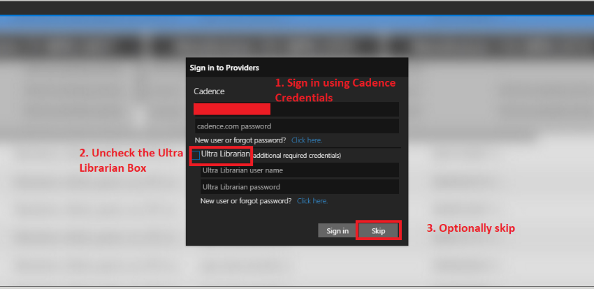
Section titled “Module 2”The first learning module of the course gives a general overview of creating and opening projects as well as the user interface of the schematic editor. The first lab will require you to the set the CDS_SITE system variable. The OrCAD Capture Constraint Manager PCB Flow section of this guide page has some images and a short description to guide you through modifying system variables. Setting the CDS_SITE variable to the proper directory is important as this specifies different setup and layout settings and contains different libraries you will need access to. Once you get around to launching the System Capture application you will be prompted to select a product. If you are using the 22.1 software use the Allegro System Capture Venture product. If you are using the 17.4 software then choose the PCB Designer product. When you first open or create a project try to use View>Panels>Unified Search to open the Unified Search window. This window may prompt you to sign in. You can sign in here to access the SamacSys tab which allows you to search for parts from external libraries. Make sure to uncheck the Ultra Librarian box when signing in. Additionally you can skip the sign in if you only need to search for or place parts from local libraries.
Module 3
Section titled “Module 3”The third module covers creating a new project and tailoring project settings. This includes graphics in the schematic editor such as modifying how the grid is displayed and changing the page setup as well as editing user preferences. This section is fairly straightforward but is critical to getting started.
Module 4
Section titled “Module 4”Module 4 dives into editing or creating libraries and library parts. It is important to note that when you are creating a library, the path name to the library does not contain any spaces in it as this will cause an error. Also keep in mind that if you change any directory names within the path that are also contained in the CDS_SITE path, the CDS_SITE variable will not update. Thus if you change a path name make sure to update the CDS_SITE variable as well.
Module 5
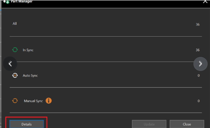
Section titled “Module 5”This module goes over the basics of schematic design in the System Capture software. This includes placing parts, wires, buses, bus taps, etc. Module 5 also introduces Version Control, a unique feature which allows users to view and switch to previous versions of a design. If you encounter any issues when trying to commit a new version to the version history the most likely culprit is the Part Manager. Before committing the part manager may need to be updated. To do this go to Tools>Part Manager then in the part manager window choose Update. This should solve the issue, however if there are parts which need to be manually synced this can be more challenging. This issue will be discussed in the module 8 section of this guide.
Module 6
Section titled “Module 6”Module 6 covers hierarchical designs as well as importing design files from other Cadence products and importing user-created libraries. The lab of this section will have you use the Project Manager and DE-HDL software. If you have never launched these products before then choose the Allegro Venture PCB Designer Suite product regardless of the software edition you are using.
Module 7
Section titled “Module 7”This module introduces the constraint manager once again. Using the constraint manager in System Capture is very similar to using it in OrCAD Capture or DE-HDL, so this module should seem pretty familiar at this point. Make sure to still be thorough when going through the labs as the changes made in the constraint manager are important for when the design is transferred to the PCB Editor.
Module 8
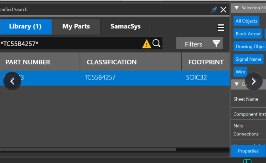
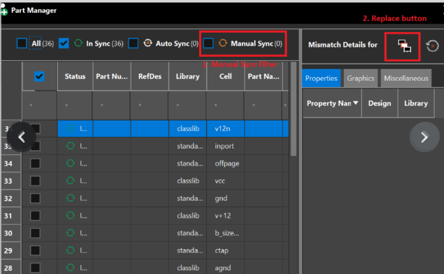
Section titled “Module 8”The final learning module covers transferring the design from the schematic editor to the PCB Editor as well as back annotating the schematic from the PCB Editor. This module’s labs gave me quite a bit of issues, the first of which involved the part manager again. The first lab involves generating a netlist, however an error was prompted when trying to do this due to the part manager not being updated. However this time the part manager could not be auto updated because it needed a part to be manually updated. For this instance the part that needed updating was the RAM TC55B4257 part. To manually update a part there are two ways to go about it. First you can open the part manager and select Details. From here filter the list of parts by Manual Sync and then select the Select a part for replacement button for the part that needs to be manually synced. In my case this didn’t work so I chose the second way to solve this issue. I simply used the unified search to find a library version of the chip I needed and replaced all the parts that needed to be manually synced.
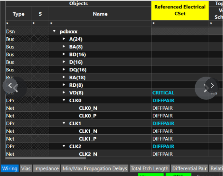
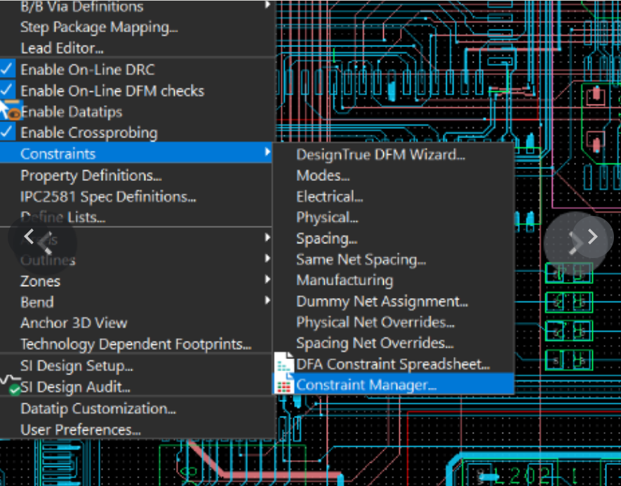
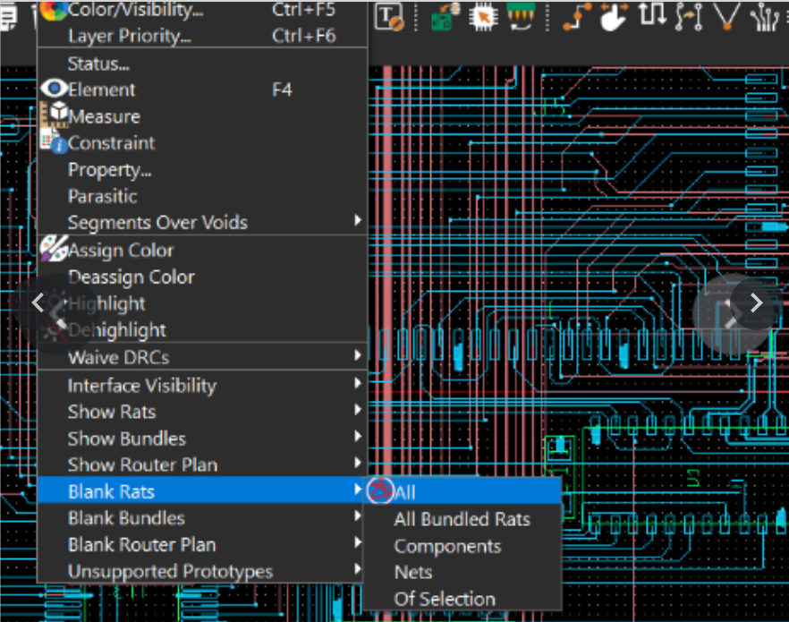
The second issue involved placing parts in the PCB Editor. For some reason the DAAMP parts could not be placed as one group in a predetermined pattern as the lab said they could be. The workaround for this is easy. The lab manual has a picture of the layout so the parts can be placed manually by using the image as a guide for which parts to place and where to place them. Later the lab asks you to display rats nest lines using cross referencing between the two programs. This may cause some trouble so to display the rats nest lines using only the PCB Editor you can start by clicking Display>Show Rats>All. Next click Display>Blank Rats>All. After this open the constraint manager by choosing Setup>Constraints>Constraint Manager. Once open simply click on whatever net you’d like to display it’s rats nest lines. The final issue is one that you may have encountered already. When the lab asks you to auto route the PCB design, this must be done in the 17.4 software as we do not have access to the auto routing license on the 22.1 software. For detailed instructions on how to do this refer to the Allegro Design Entry HDL Front-to-Back Flow section of this guide page.
Resources
Section titled “Resources”The SamacSys website. They create PCB libraries, schematic symbols, and PCB footprints, may be cool to do some digging on their site.
Component Search Engine website, can be used to search for parts, very similar to the Unified Search window in System Capture.