Allergo PCB Editor Intermediate Techniques v22.1
By Jarret
General Notes
Section titled “General Notes”-
Here is the link to the course.
-
Follow the same steps as above for starting this project; however, DO NOT download the lab database into OneDrive (or any form of online storage), as this may cause problems later in the course
-
I actually enrolled in the 22.1 version of the course but used the 17.4 version of the software, and I did not encounter any issues. Currently, we are using the 17.4 version of the software due to the 22.1 version not being fully licensed for Clemson students yet.
-
When the lab PDF tells you to save the project, and an error comes up when you do this, first check if the lab PDF says anything about errors coming up. If it does, you are good to move on. If it does not, click on the error to see if you can fix it before moving on.
-
A mouse is highly recommended for this course.
Requirements
Section titled “Requirements”-
Access to PCB Editor 17.4
-
Access to Project Manager 17.4
-
Access to Padstack Editor 17.4
Module 1 and Database Downloads
Section titled “Module 1 and Database Downloads”Module 1 of the course simply contains an overview of what the course will cover. It is still important to read over this and gather an understanding of what you will be learning. Before starting the course you should head to the Database Downloads module of the course. On the Module 1 page, click “Database Downloads” and save the folder “Lab Database” to a location on your computer. I recommend making this folder easy to access as you will be navigating to it a lot throughout the course. Right-click on this folder, and click “Extract all”. Also, open up the “Lab PDF” in a new tab.
Module 2
Section titled “Module 2”-
When you first open PCB Editor, choose “Allegro PCB Venture” as your product if you do not already have it chosen.
-
When directed to use the DFA Symbol Update program, just search this app in your windows search bar and it should come up.
In lab 2, they actually give you a little bit of a task where you use the Display-Measure command and change the DFA Constraints to match the DRC error picture in the Lab. You will actually be changing the constraint value for the Vertical and Horizontal air gap so it is important to know what the initial is to find estimate a value to give you the desired results.
Module 3
Section titled “Module 3”In the first lab of this module, you go through a bunch of different .brd files to practice editing the routing of wires. Most of them are very explanatory and if you have any trouble just restart from when you open a certain .brd file and you should be good to go.
Module 9
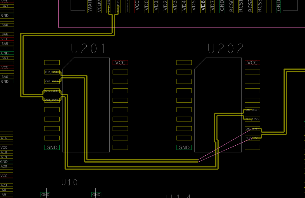
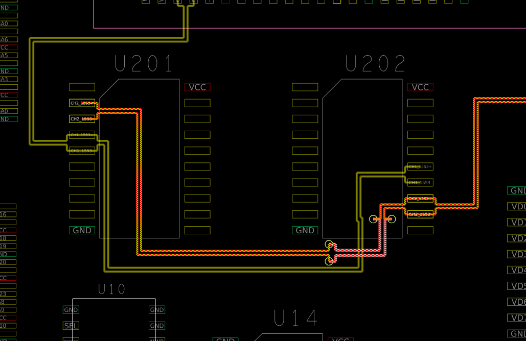
Section titled “Module 9”In lab 1 and 2 of this module, the main part I got stuck on is routing the differential pairs. This would be easy, but you need to route some of the connections on the int layers of the board using vias. To do this, go ahead and route as many of the connections as you can before you need to cross some of them. (Seen below in picture to the left). Once you are done with this, go ahead and change the alternate layer in the options tab to “Int 1”, then, right click to “Via Pattern” and select whatever via pattern works best with your current wire direction. Then right click and choose “Add Via”, then you can route across the other wires. Now, right click again and choose “Via Pattern” and then “Add Via” and finish the wiring to the destination differential pair. (Seen below in picture to the right).
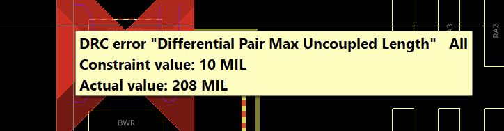
In addition to this, in the end of lab 1, you are tasked to change the Max Uncoupled Length to get rid of the DRC’s. If you hover your cursor over the DRC error it tells you the actual value which easily allows you to change the Max Uncoupled Length to get rid of the DRC.
Module 12
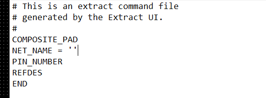
Section titled “Module 12”For this module, you are required to create .txt files that when run using extracta, display the correct values told by the lab to retrieve from the file. To do this, it is recommended to watch all of the lecture videos all the way through. This gives you a good sense of how to write these files.
The way I recommend writing these files is by going into tools, reports, NEW/EDIT, then use this to start off with all the components needed. Once you save this file, go to it and make any needed changes to the code.
Below, you can see how I wrote the code to solve lab 1. First, for the group, there are probably multiple different options that would work but I chose Composite_Pad. Then I selected “NET_NAME,” “PIN_NUMBER,” and “REFDES,” as these are the three requested by the lab. I then saved this file, and went into Notepad on windows to edit it, adding the ” = ” ” next to the NET_NAME line. This makes it so the report only includes those pins that are unused.