
Allegro Design Entry Using OrCAD Capture
By Jarret
Requirements
Section titled “Requirements”Access to OrCAD Capture software
No prior knowledge of circuit design is needed for this course
General Notes
Section titled “General Notes”-
Here is the link to the course.
-
This course serves as an introductory class into using the Capture software, teaching actions such as opening projects, creating schematics, placing parts, routing, etc. Since it is an introduction, this course is fairly straightforward, though some later modules become slightly more complex. This course does offer a badge, so remember to take notes and pay close attention to the lectures.
-
DO NOT download the lab database into OneDrive (or any form of online storage), as this caused problems down the line for me archiving the project, etc.
-
I actually enrolled in the 22.1 version of the course but used the 17.4 version of the software, and I did not encounter any issues. Currently, we are using the 17.4 version of the software due to the 22.1 version not being fully licensed for Clemson students yet.
-
When the lab PDF tells you to save the project, and an error comes up when you do this, first check if the lab PDF says anything about potential errors coming up when saving the project. If it does, you are good to move on. If it does not, click on the error to see if you can fix it before moving on.
Module 1
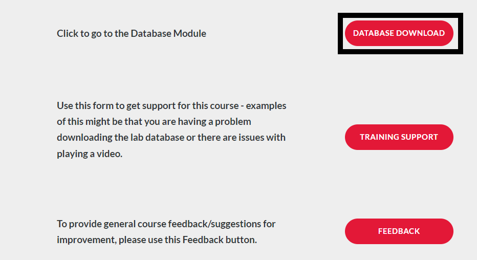
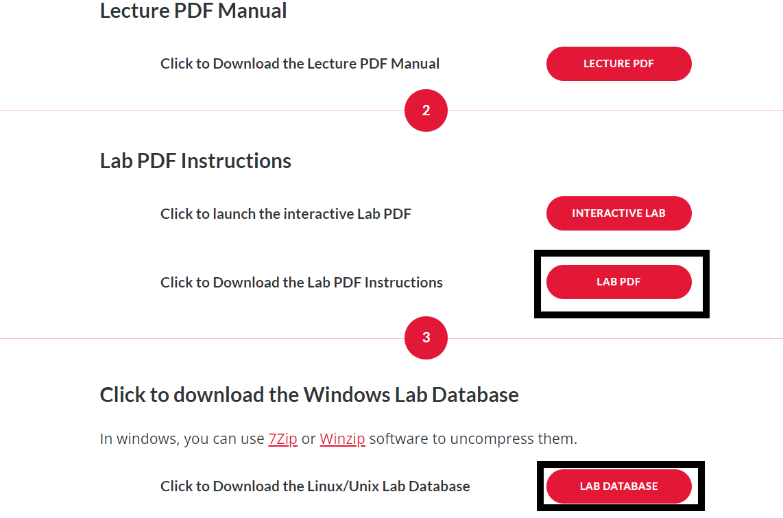
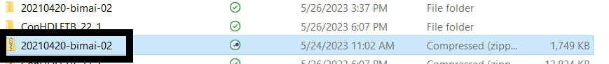
Section titled “Module 1”On the Module 1 page, click “Database Downloads” (also located at the bottom of the page) and save the folder “Lab Database” to a location on your computer. I recommend making this folder easy to access as you will be navigating to it a lot throughout the course. Right-click on this folder, most likely called “20210420-bimai-02” and click “Extract all”. Also, open up the “Lab PDF” in a new tab. See below.
Module 2
Section titled “Module 2”This module provides great information on getting started with the Capture CIS software. It covers everything regarding opening the correct software, setting the correct environment variables, opening projects, navigating your projects, and the basic UI functionalities of the software. Please note that when launching the Capture CIS 2022 software, you’ll want to select “Allegro PCB Design CIS L” product choice. It has a different name than the “OrCAD Capture” option they mention in the videos for this module, but it’s the same thing.
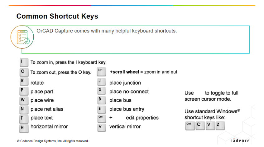
Another useful portion of this module is the slide showing the common shortcut keys. These will be extremely useful if you use this software frequently and want to be able to work a little more efficiently.

Other than this, the labs are what you’re going to want to focus most of your energy to. The videos for each of the modules give in-detail information and the demo videos are nice for seeing things in action, but personally, I’ve found that the best way for me to learn using these Cadence training courses is to skim the videos for keywords and important info and then to jump right into the lab assignments.
Module 3
Section titled “Module 3”This module works through the different preferences that you can use to set up your software’s environment in the way which works best for you. One of the important parts about this module is the video on the Title Block Tab, which is extremely for making sure all the right info is on your project if you’re turning it in for some assignment. Other than that, I suggest paying attention to the “Creating a Design Template” demo video and then working on the labs, which will step you through the same process shown in the demo video for setting preferences and making your design template.
Note: In part 5, the lab says to simply add “\ram” to the end of the file path, which should be done, but first I would recommend going and creating the ram folder within the ftb folder in your file manager. Some computers may not automatically create the folder when a path which points to a file that does not exist is entered, and will prompt an error instead.
Module 4
Section titled “Module 4”Module 4 introduces you to the concepts of libraries in Capture. Libraries are where are the parts that you may want to use will be stored, so it’s important to understand this concept if you plan on making any sort of schematic designs with Capture. The most important sections of this module are the ones detailing how to copy parts from one library to another, as this will be a lot of help in creating any of your own libraries.
Additionally, understanding how to create your own parts is EXTREMELY important for any sort of schematic work. It’s also key to understand the differences between homogeneous and heterogeneous parts: a homogeneous part is a part with ONE symbol defining it that contains either one part only or multiples of the same part, each with their own pins (single-section). A heterogeneous part has multiple, unidentical parts within a single package (multi-section). The differences between these two classifications becomes more clear if you follow through the videos and the demos for creating the two different types of parts.
The next important section of this module is the “Generating a Part from Imported Data” section, which basically describes how to use manufacturer information as a shortcut to create parts automatically. This sort of method will come up again for creating entire schematics from spreadsheet data.
Module 5
Section titled “Module 5”Module 5 brings together a lot of the previous information to show you how to begin creating your own schematics by hand. It’ll cover a lot of the interfacing methods and UI options for schematic creation, as well as some tips and tricks to make this process quicker.
Module 5 also covers Design Rules Checks, which is one of the more important tools in the Capture software. This will allow you to automatically check your schematics and your work to ensure that everything is connected properly and is within your defined specs. It’s super useful for double-checking work before you turn something in or move on to the next stage of a project.
Module 6
Section titled “Module 6”Module 6 is one of the modules where the Labs are key. Since most of the videos for this module cover technical processes like how-to’s for creating schematics, it might be easier to just start on the labs right away and then reference the videos for help if you run into any trouble. The videos contain a lot of useful information on the specifics of how things work for this type of schematic creation — it is very important to pay thorough attention to them in order to understand what each constraint manager page is used for and what properties they can control — but the Labs are where you’ll get the really useful practice of working through these examples on your own.
Module 7
Section titled “Module 7”Module 7 covers part properties for parts in schematics. Other than actually creating your schematic design, I feel like knowing how to manage the properties of your parts in your design is the next most important thing. From my experience in personal projects, I’ve found myself spending a majority of my time on Capture editing and changing around part properties, since these control the different values for components as well as their physical properties, which come into play a lot when you are creating a PCB off of one of your Capture schematics. This will also come in handy a ton when creating your Bill of Materials (BOM) for a project, since this will be created directly off of your part properties.
Pay attention to the labs regarding using spreadsheet information for part properties - this is a trick I wish I knew about when I was designing some of my own schematics, as it can cut down hours of time to minutes since using this skill will eliminate the need to manually change each part’s properties.
Module 8
Section titled “Module 8”Module 8 covers creating hierarchical designs. Hierarchical just means that you have a design which contains sub-circuits consisting of other schematic designs. Think of it like how your computer may have a main design for the motherboard, but then sub-designs for each of the components connecting to the motherboard like the CPU and the RAM. Hierarchical designs are super important for modularizing your projects, especially if you repeatedly use certain sub-circuits in your designs or have a large schematic.
The other important section of this module is the section regarding netlists. A netlist is how you’ll be able to create a PCB from your schematic, and if you have errors or mistakes in your part properties when you create your netlist, it may lead to lots of issues and errors down the road for your design process.
Module 9
Section titled “Module 9”Module 9 is just a simple summary of the topics covered in the course. Once you’ve gotten here, congratulations! You should be all done with this training course, and all you have left to do will be to complete the course evaluation and take your badge exam.